Adding MELFA
The system configuration when using Mitsubishi Electric FA allows for configuring a MELFA device within the Workbench. The displayed items vary depending on the selected device and communication path.
Notes:
- MELFA devices can only be edited when disabled. When the device is activated, settings cannot be changed until the device is disabled. See Activating and Disabling a Mitsubishi FA Device.
-
In addition to normal device readout, this MELFA connection also supports the readout by CPU buffer memory extended function. To retrieve the data of MELFA devices through the CPU buffer memory extended function, it is necessary to configure the CPU buffer memory extended function in MELSEC and MELFA. This can be done by changing the "IQMEM" robot parameter setting. The "IQMEM" parameter for selecting the CPU buffer memory extended function is 16-bit data. Set the bit 0 to one to use the extended functions. For more details, please refer to the chapter 2 "Preparation for Using Extended Function" in the CR800-R/CR800-Q series controller iQ Platform Supporting Extended Function Instruction Manual on the Mitsubishi Electric FA website:
- When you have added a MELFA device, predefined tags will be added under the device. If you monitor these tags without the screens generated from Asset Builder, it is necessary for you to take the following steps with the engineering tool for MELSEC or MELFA. Please also refer to the CR800-R/CR800-Q series controller iQ Platform Supporting Extended Function Instruction Manual on the Mitsubishi Electric FA website:
References and Procedures
|
Reference |
Procedure |
|---|---|
|
3.1.1 Select Monitoring Items |
Set the following bits in the sequencer output data, Function selection (Sequencer Addr: 512), to Valid(1). * bit2: Monitor operation control settings * bit3: Monitor activities * bit4: Monitor current and aimed positions * bit5: Monitor position and joint information * bit6: Monitor maintenance information |
|
3.1.2 Select Target Mecha |
Set the sequencer output, Specify a mecha number (Sequencer Addr: 841), to 1. |
|
3.2.4 Monitor Position and Joint Information |
Set the sequencer output, Joint data selection-1(Sequencer Addr: 851), to Current feedback(8). |
|
3.2.4 Monitor Position and Joint Information |
Set the sequencer output, Joint data selection-2(Sequencer Addr: 852), to Axis load level(12). |
To add a MELFA device:
-
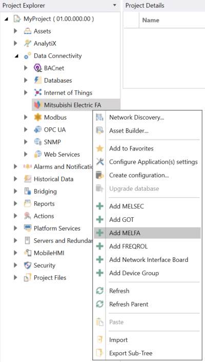
Open Workbench and in Project Explorer, expand your project > Data Connectivity, right-click Mitsubishi Electric FA, and select Add MELFA.
-OR-
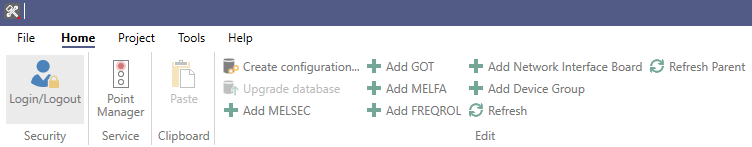
Select the Mitsubishi Electric FA node in Project Explorer, and then click the Add MELFA button in the Edit section of the Home ribbon.
This opens the MELFA properties dialog in the central panel of Workbench.
-
In the Name text entry field, enter a name for the MELFA device.
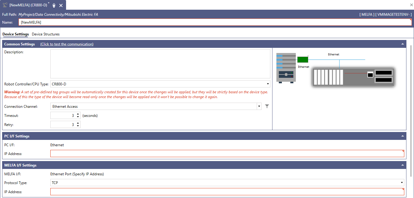 The system image of the selected Connection Channel displays the configuration diagram of the server and device based on the selected CPU series, CPU type, and Connection Channel.
 -
In the Common Settings section, set up the following:
- (Click to test the communication): Click this link to connect to the actual device for a test.
- Description: Enter a description of the MELFA device in the text entry field.
-
Robot Controller/CPU Type: Use the drop-down list to select a robot controller or CPU type. The selectable controllers and robots are as follows: CR800-D, R16RT and Q172DSR.
To maintain consistency with automatically generated tags, changes cannot be made after clicking Apply. -
Connection Channel: Select the connection channel from the drop-down list. Based on the selected robot controller or CPU type, the connection channels are displayed as follows.
- If CR-800-D is selected: Ethernet Access
- If R16RT is selected: USB Access, Ethernet Access, Ethernet Module Access, CC-Link IE Control Module Access
- If Q172DSR is selected: USB Access, Ethernet Access, Ethernet Module Access, CC-Link IE Control Module Access
See MELFA System Configuration for additional compatible system-related details.
The system image of the selected Connection Channel next to the Common Settings section displays the configuration diagram of the server and device based on the selected CPU series, CPU type, and Connection Channel. - Click the
 button next to the Connection Channel text entry field to display the Select Connection Channel dialog, and configure the settings. For more details, please refer to Connection Channel Details.
 - Timeout: Enter a timeout in seconds to cease communication attempts upon error. Use the text entry field or the up/down arrow buttons.
- Retry: Enter a number of communication retries. Use the text entry field or the up/down arrow buttons.
-
In PC I/F Settings, set up the following:
- PC I/F: The PC I/F (interface function) related to the connection channel selected in the Connection Channel is displayed.
- IP Address: Enter the IP address for the PC I/F (interface function) in the text entry field.
- Source Network Number: Enter a source network number (default 1, upper bound is 239). Use the text entry field or the up/down arrow buttons.
- Source Station Number: Enter a source station number (default 1, upper bound is 120). Use the text entry field or the up/down arrow buttons.
- Board Number: Use the drop-down list to select from the 1st Module to the 4th Module for CC-Link IE Control Board.
-
In MELFA I/F Settings, set up the following:
- MELFA I/F: The MELFA I/F related to the connection channel selected in the Connection Channel is displayed.
- Protocol Type: Use the drop-down list to select either TCP or UDP.
- IP Address: Enter an IP address for the MELFA I/F in the text entry field.
-
Network Number: Enter a network number. Use the text entry field or the up/down arrow buttons.
For connection settings where the Source Network Number is configured, the same value is automatically set. - Station Number: Enter a station number. Use the text entry field or the up/down arrow buttons.
-
In Multiple CPU Settings, set up the following:
-
Target System: Based on the selected robot controller or CPU type, it is displayed as follows:
- If CR-800-D is selected: Single CPU
- If R16RT or Q172DSR is selected: Multiple CPU
-
Target PLC: Use the dropdown list to select a PLC. The selectable PLCs are as follows:
- If CR-800-D is selected: Not Specified
- If R16RT or Q172DSR is selected: PLC No.2, PLC No.3, PLC No.4
-
Multiple CPU input offset: Enter the input offset number for the multiple CPU. Use the text entry field or the up/down arrow buttons.
The offset value is determined by the unit number and the manually entered offset value (parameter: QMLTCPUS). If the offset is not manually set on the robot CPU side, please refer to the following values.
- If PLC No.2 is selected: 0
- If PLC No.3 is selected: 1
- If PLC No.4 is selected: 2
For more details on the QMLTCPUS parameter, please refer to the CR800-R/CR800-Q series controller iQ Platform Supporting Extended Function Instruction Manual:
- Click the Check Offset button to display the Check Multiple CPU Input Offset dialog. Please refer to Check Offset Details for more information.
-
- In the Other Settings section in Merge Gap, enter the value that indicates the number of non-contiguous registers that can be batch-read in a single communication between Mitsubishi Electric FA and MELFA devices. This value should be set larger than the number of I/O address points between the tags. If the value is too small, multiple communications will be required to read the data. This setting is for adjustment purposes, and is usually recommended to leave it at the default value of 64. Please refer to Merge Gap Details for more information.
- If necessary, configure the structures on the Device Structures tab, and then click Apply to save your changes to the configuration, and Close to return to Workbench. For more details, refer to How to Add a Structure to Your Device.
See Also: