Adding a Tag Group
A tag group allows you to create a list of tags associated with a Mitsubishi Electric device.
The items set in the tag group vary depending on the device. For details, please refer to the following table.
The List of Tag Settings Items
|
Item |
Device |
||||
|---|---|---|---|---|---|
|
|
MELSEC |
GOT |
FREQROL |
MELFA |
Network Interface Board |
|
Click to import global labels from a file |
✓ |
✓ |
|
|
|
|
Click here to add new item |
✓ |
✓ |
✓ |
✓ |
✓ |
|
Name |
✓ |
✓ |
✓ |
✓ |
✓ |
|
Enable |
✓ |
✓ |
✓ |
✓ |
✓ |
|
MELFA Device Parameter |
|
|
|
✓ |
|
|
Status Variable |
|
|
|
✓ |
|
|
Slot Number |
|
|
|
✓ |
|
|
Start Number |
|
|
|
✓ |
|
|
Name for I/O |
✓ |
✓ |
✓ |
✓ |
✓ |
|
I/O Address |
✓ |
✓ |
✓ |
✓ |
✓ |
|
Data Type1 |
✓ |
✓ |
✓ |
✓ |
✓ |
|
Array Settings |
✓ |
|
✓ |
✓ |
✓ |
|
String Length |
✓ |
|
✓ |
✓ |
✓ |
|
Polling Rate2 |
✓ |
✓ |
✓ |
✓ |
✓ |
|
Description |
✓ |
✓ |
✓ |
✓ |
✓ |
1 The displayed data types vary depending on the device.
2 The rates vary depending on the device.
When adding a MELFA or FREQROL device, the necessary tags to display the template screen in Asset Builder are automatically created.
To add a tag group:
-
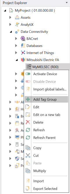
Open Workbench and in Project Explorer, expand your project > Data Connectivity > Mitsubishi Electric FA. Right-click the desired Mitsubishi Electric device and select Add Tag Group.
-OR-
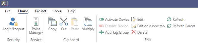
Select the Mitsubishi Electric FA node in Project Explorer, and then click the Add Tag Group button in the Edit section of the Home ribbon.
This opens the Tag Group properties dialog in the central panel of Workbench.
-
In the Name text entry field, enter a name for the tag group.
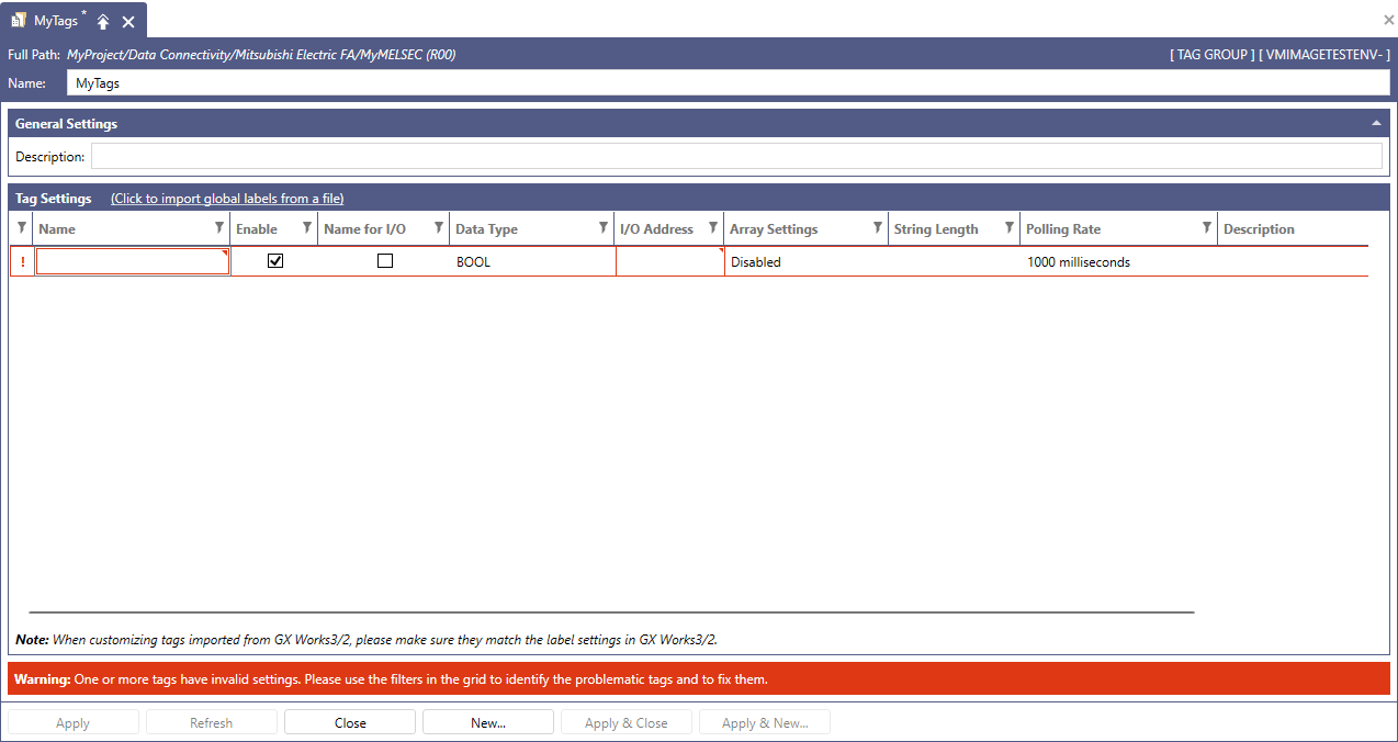
- In the Description section, enter a description for the tag group.
-
In the Tag Settings section, add and configure the desired tags. From the following list of all available settings for all device types, select the ones that apply to the Tag Settings chart for your device.
-
Click to import global labels from a file: Click this link to import global labels as tags.
The button name varies depending on the device type.This function is supported by MELSEC and GOT, and they support importing the following files.
- [MELSEC] CSV file exported from GX Works2
- [GOT] Unicode text file exported from GT Designer3
- [GOT] CSV file exported from GT Designer3 with the display language set to English
- Click here to add new item: Click this link to add a new tag to the Tag Settings section.
- In the Name column, enter a name for the new tag. This field has a fixed position, so when you scroll horizontally, it is always visible.
- Select the Enable checkbox to enable the tag. This field has a fixed position, so when you scroll horizontally, it is always visible.
-
MELFA Device Parameter: Use the drop-down list to select the target from which to read the parameters. Depending on the selected parameter, there are restrictions on the functions that can be selected for other items. For details, please refer to the following table.
Restrictions of Each Setting Item
MELFA Device Parameter
Editability and Required Elements
Range
Status Variable
Slot Number
Start Number
Name for I/O,
I/O Address
Array Settings
Data Type
Error Information
-
-
✓
-
fixed at (0...42)
INT, UINT, WORD
Program Information
-
✓
-
-
fixed at (0...71)
INT, UINT, WORD
Product Information
-
-
-
-
fixed at (0...28)
INT, UINT, WORD
Status Variable (Integer)
✓
✓
-
-
fixed at Disable
INT, UINT, WORD
Status Variable (Long-precision integer)
✓
✓
-
-
fixed at Disable
DINT, UDINT, DWORD
Status Variable (single-precision real number)
✓
✓
-
-
fixed at Disable
REAL
Status Variable (Position)
✓
✓
N/A
N/A
fixed at (0...19)
INT, UINT, WORD
Status Variable (Joint)
✓
✓
N/A
N/A
fixed at (0...15)
INT, UINT, WORD
Not Specified
N/A
N/A
N/A
✓
Editable
All1
1When Not Specified is selected, the same data types as MELSEC can be selected.
Please refer to the following reference documents for more information:
CR800 Series Controller INSTRUCTION MANUAL Detailed explanations of functions and operations
CR800-D/R/Q controllers Predictive Maintenance Function User’s Manual
CR800-D series controller GOT Direct Connection Extended Function Instruction Manual
-
Status Variable: Enter the status variable name with the maximum length of 255 characters and only containing alphanumeric characters, underscores, parentheses, or commas.
Please refer to the following document on the Mitsubishi Electric FA Web page:
CR800 Series Controller INSTRUCTION MANUAL Detailed explanations of functions and operations
CR800-D/R/Q controllers Predictive Maintenance Function User’s Manual
-
Slot Number: Use the drop-down list to select the slot number.
Select 1 to 32 if MELFA Device Parameter is Program Information, and 0 to 32 for other parameters. For external variables, specify 0.
For more details, please refer to the following document on the Mitsubishi Electric FA Web page:
CR800-D series controller GOT Direct Connection Extended Function Instruction Manual
-
Start Number: Use the drop-down list to select the starting position for retrieving the error number.
Please refer to CR800-D series controller GOT Direct Connection Extended Function Instruction Manual
- Name for I/O: Select the checkbox to use the Name field as the I/O Address.
-
I/O Address: Enter the I/O address. The address name varies depending on the type of Mitsubishi Electric FA device selected, so please refer to the "Accessible Registers" for each Mitsubishi Electric FA device for details.
If the Name for I/O checkbox is selected, the string specified in the Name field is displayed in this field and used as the I/O address value. -
Data Type: Use the drop-down list to select the tag's data type. For the supported data types for each device, please refer to the table below. Similarly to the Device Structures displayed in the settings of each device, you can also configure tags with complex structures in the tag settings. For more details, refer to How to add a Structure to your device.
The List of Data Type settings
Device
Setting Value
MELSEC3
BOOL1, WORD, DWORD, INT, UINT, DINT, UDINT, LINT, ULINT, REAL, LREAL, STRING, WSTRING, STRUCTURE2
FREQROL
MELFA4
Network Interface Board
GOT
BOOL1, INT, UINT, DINT, UDINT, BCD16, BCD32, REAL
1The BOOL value can be used by specifying the bit position (for example, EG0.1)
2The name of a device structure is displayed in parentheses.
3All data types support the array type.
4The displayed data type varies depending on the parameters set in the MELFA Device Parameter.
-
Array Settings: To display the Array Configuration dialog, click into the field, and then click
 . Then specify the array settings and click OK. If the tag is an array type, the cell displays the shape of it (for example, (0..2) for a single-dimensional array with 3 elements). If the tag is not an array type, the cell displays Disabled.
 -
String Length: If the tag is a STRING or WSTRING type, the cell displays the length of the string (default: 32). The length of the string can be changed between 1 and 255. If the tag is not a string type, the cell is blank.
-
Polling Rate: Use the drop-down list to select the tag's polling rate. Please refer to the following table for the rates that can be set for each device.
The List of Polling Rate Settings
Device
Setting Value
MELSEC
50, 100, 200, 500, 1000, 2000, 5000 milliseconds
GOT
FREQROL
50, 100, 200, 500, 1000, 2000, 5000 milliseconds and 1, 10 minutes
MELFA
Parameter is Not Specified
50, 100, 200, 500, 1000, 2000, 5000 milliseconds
MELFA
Parameter is other than Not Specified1
1000, 2000, 5000 milliseconds and 1, 10, 60 minutes
Network Interface Board
50, 100, 200, 500, 1000, 2000, 5000 milliseconds
1Tags other than Not Specified selected in MELFA Device Parameter cannot be acquired in parallel, and only one tag can be acquired per second. Therefore, when multiple tags are set, acquiring them at the specified cycle may not be possible.
-
Description: Enter a description to distinguish this specific tag.
-
- When finished, click Apply to save your settings, and then Close to return to Workbench. Your tag group will be added to the Project Explorer tree structure.
See Also: