Adding MELSEC
The system configuration when using Mitsubishi Electric FA allows for configuring a MELSEC device within Workbench. See MELSEC System Configuration for more information. The displayed items vary depending on the selected device and communication path.
To add a MELSEC device:
-
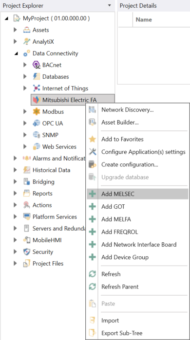
Open Workbench and in Project Explorer, expand your project > Data Connectivity, right-click Mitsubishi Electric FA, and select Add MELSEC.
-OR-
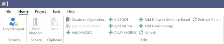
Select the Mitsubishi Electric FA node in Project Explorer, and then click the Add MELSEC button in the Edit section of the Home ribbon.
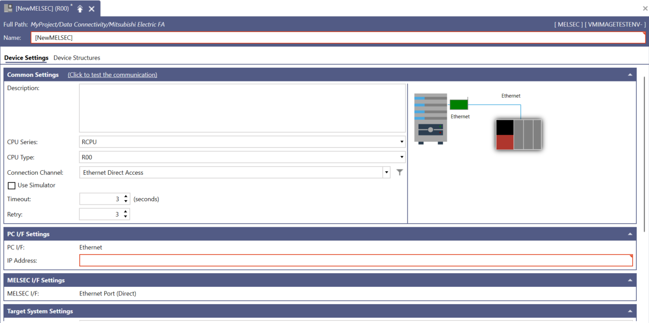
This opens the MELSEC properties dialog in the central panel of Workbench.
-
In the Name text entry field, enter a name for the MELSEC device.
-
In the Common Settings section, set up the following:
- (Click to test the communication): Click this link to connect to the actual device for a test.
- Description: Enter a description of the MESEC device in the text entry field.
-
CPU Series: Use the drop-down list to select the CPU series. Selectable CPU Series are as follows: RCPU, RSafety, LHCPU, FX5CPU, QCPU, LCPU, FXCPU, QSCPU, MXR, MXF.
See MELSEC System Configuration for additional compatible system-related details.
-
CPU Type: Use the drop-down list to select the CPU type. The options are based on the selected CPU Series.
- If the RCPU CPU series is selected: R00, R01, R02, R04, R08, R16, R32, R120, R04EN, R08EN, R16EN, R32EN, R120EN, R08P, R16P, R32P, R120P, R08PSF, R16PSF, R32PSF, R120PSF
- If the RSafety CPU series is selected: R08SF, R16SF, R32SF, R120SF
- If the LHCPU CPU series is selected: L04H, L08H, L16H
- If the FX5CPU CPU series is selected: FX5U/FX5UC, FX5UJ, FX5S
- If the QCPU CPU series is selected: Q00UJ, Q00U, Q01U, Q02U, Q03UD, Q03UDE, Q03UDV, Q04UDH, Q04UDEH, Q04UDV, Q04UDPV, Q06UDH, Q06UDEH, Q06UDV, Q06UDPV, Q10UDH, Q10UDEH, Q12PRH, Q13UDH, Q13UDEH, Q13UDV, Q13UDPV, Q20UDH, Q20UDEH, Q25PRH, Q26UDH, Q26UDEH, Q26UDV, Q26UDPV, Q50UDEH, Q100UDEH
- If the LCPU CPU Series Selected: L02S/L02S-P, L02/L02-P, L06/L06-P. L26/L26-P, L26-BT/L26-PBT
- If the FXCPU CPU series is selected: FX3S, FX3G/FX3GC, FX3U/FX3UC/FX3UC-32MT-LT-2
- If the QSCPU CPU series is selected: QS001
- If the MXR CPU series is selected: MXR300-16, MXR300-32, MXR300-64, MXR500-128, MXR-500-256
- If the MXF CPU series is selected: MXF100-8-N32, MXF100-8-P32, MXF100-16-N32, MXF100-16-P32
See MELSEC System Configuration for additional compatible system-related details.
-
Connection Channel: Select the connection channel from the drop-down list. Based on the CPU Series and CPU type, the available connection channels are displayed.
The system image of the selected Connection Channel next to the Common Settings section displays the configuration diagram of the server and device based on the selected CPU series, CPU type, and Connection Channel. - Click the
 button next to the Connection Channel text entry field to display the Select Connection Channel dialog, and configure the settings. For more details, please refer to Connection Channel Details.
 -
Use Simulator: Select the checkbox to use simulators and enable the simulator settings.
QSCPU does not support using a simulator, and this option is grayed out when one of these PLC series is selected. - Timeout: Enter a timeout in seconds to cease communication attempts upon error. Use the text entry field or the up/down arrow buttons.
- Retry: Enter a number of communication retries. Use the text entry field or the up/down arrow buttons.
-
In PC I/F Settings, set up the following:
-
PC I/F:The PC I/F (interface function) related to the connection channel selected in the Connection Channel is displayed.
See MELSEC System Configuration for additional compatible system-related details.] - IP Address: Enter the IP address for the PC I/F (interface function) in the text entry field.
- COM Port Number: Enter a COM port number for the PC I/F (interface function) in the text entry field (or use the "up/down" arrow buttons).
- Source Network Number: Enter a source network number (default 1, upper bound is 239). Use the text entry field or the up/down arrow buttons.
- Source Station Number: Enter a source station number (default 1, upper bound is 120). Use the text entry field or the up/down arrow buttons.
- Board Number: Use the drop-down list to select from the 1st Module to the 4th Module for CC-Link IE Control Board.
-
-
In MELSEC I/F Settings, set up the following:
-
MELSEC I/F: The MELSEC I/F (interface function) related to the connection channel selected in the Connection Channel is displayed. Note that some of the settings in the remainder of this section may be active or inactive based on the selection of the specific CPU Series, CPU Type, and PC I/F combinations.
See MELSEC System Configuration for additional compatible system-related details. - Protocol Type: Use the drop-down list to select either TCP or UDP.
- Network Number: Enter a network number. Use the text entry field or the up/down arrow buttons.
- Station Number: Enter a station number. Use the text entry field or the up/down arrow buttons.
- IP Address: Enter an IP address for the MELSEC I/F in the text entry field.
- Baudrate: Use the drop-down list to select a baudrate from 9600, 19200, 38400, 57600, or 115200.
- Control: Use the drop-down list to select from DTR Control, RTS Control, DTR and RTS Control, and DTR or RTS Control.
-
-
In Connection I/F Settings, set up the following:
- Connection I/F: The Connection I/F related to the connection channel selected in the Connection Channel is displayed.
- Network Number: Enter a network number. Use the text entry field or the up/down arrow buttons.
- Station Number: Enter a station number. Use the text entry field or the up/down arrow buttons.
-
In Target System Settings, set up the following:
-
Target System: Use the drop-down list to select from either Single CPU or Multiple CPU.
When Redundant CPU is specified, GENESIS can connect to the CPU configured in the redundant system. Furthermore, GENESIS will automatically link to the System Switching of the redundant system and maintain the connection.
Please refer to the chapter 26.2 "System Switching" in MELSEC iQ-R Process CPU Module User's Manual on the Mitsubishi Electric FA Web page:
The configuration conditions corresponding to the CPU configured in the redundant system are as follows:
CPU Series
CPU Type
Connection Channel
RCPU
R08P, R08PSF, R16P, R16PSF, R32P, R32PSF, R120P, R120PSF
Ethernet Access, Ethernet Module Access, CC-Link IE Control Module Access
QCPU
Q12PRH, Q25PRH
Ethernet Module Access, CC-Link IE Control Module Access
-
Target PLC: Use the drop-down list to select a PLC type which is based on the selected Target System above.
- If Single CPU Selected: Not Specified
- If Multiple CPU Selected: PLC No.1、PLC No.2、PLC No.3、PLC No.4
- If Redundant CPU Selected: Control System
Notes:
- Redundant CPU is not supported by multiple networks. If multiple networks is selected in "Connection Channel", "Redundant CPU" is not displayed.
-
For details on the Control System, please refer to the following document on Mitsubishi Electric FA Web page:
MELSEC iQ-R Process CPU Module User's Manual
-
-
In Simulator Settings, set up the following:
-
System Number: Enter a number between 1 and 4 for the number of simulators to connect when using RCPU, RSafety, FX5CPU, LHCPU, MXR and MXF. Use the text entry field or the up/down arrow buttons.
This option is grayed out when the Use Simulator checkbox is cleared. -
PLC Number: Use the drop-down list to select the PLC number between 1 and 4 to connect when using RCPU, RSafety, FX5CPU, LHCPU, MXR and MXF.
This option is grayed out when the Use Simulator checkbox is cleared or when the CPU series is LHCPU or FX5CPU.
-
-
In Other Settings, set up the following:
- Merge Gap: Enter the value that indicates the number of non-contiuguous registers that can be read in a batch in a single communication between Mitsubishi Electric FA and MELSEC devices. This value should be larger than the number of registers between the tags being monitored. If the value is too small, multiple communications will be required to read the data. This setting is for adjustment purposes and is usually recommended to leave it at its default value of 64. Please refer to Merge Gap Details for more information.
- Encoding: Use the drop-down menu to select an encoding type from Not Specified, Unicode (UTF-16), Shift_JIS, GB18030, Big5, or KS X 1001. This setting applies to all tags in the STRING data type under the selected device, reading and writing to a PLC with the specified encoding. Please refer to Encoding Details for more information.
- If necessary, configure the structures on the Device Structures tab, and then click Apply to save your changes to the configuration, and Close to return to Workbench. For more details, refer to How to Add a Structure to Your Device.
See Also: