Data Items
A Data Item represents a register in the device or a range of registers. A symbolic name and description is associated with the data item. An OPC client can obtain the data item description.
The actual OPC item name (tag) is compounded from the Address Space root, the names of the folder and its subfolders, and the name of the data item. Data items can be located in any folder, even in the root of the address space.
To Add a New Data Item:
-
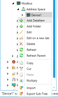
From the Project Explorer, click on a device under the Address Spacenode, then AddDataItem, as shown below.
New Data Item from the Project Explorer
-OR-
Select a device under the Address Space node in the Project Explorer, then click on the Add Data Item button (shown below) in the Edit section of the Home ribbon in the Workbench.
Add Data Item Button

-
This opens the New Data Item properties in the right side of the configurator, as shown below. In the Data ItemName field, specify a logical name for the data item (Setpoint, Param001, ON_OFF, etc).
New Data Item Properties
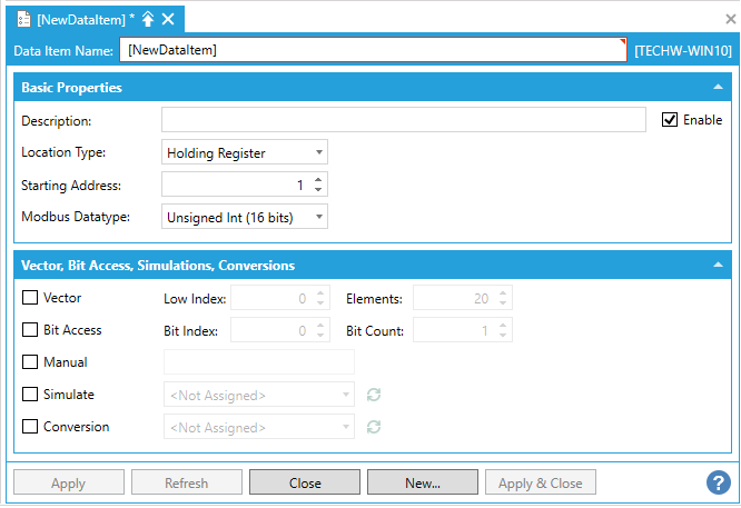
Basic Properties
-
Enable: Click this checkbox to enable the Data Item.
-
Description: Enter a descriptive comment for the data item.
-
Location Type:Location type is a type of a register in the device. Every device is identified by its unique address. Its registers are read as Input (1 bit long) or Input Register (16 bits), or written to as Coil (1 bit) or Holding Register (16 bits). Registers of each type are addressed by using 16-bit numbers. Device registers are divided into Coils, Inputs, Input Registers and Holding Registers. The table below explains the name conventions used:
|
Read Only |
Read / Write |
|
|
1 bit |
Input |
Coil |
|
16 bit |
Input Register |
Holding Register |
-
Starting Address: This value specifies the device address of the first register/coil for the data item.
-
Modbus Datatype: Select the data type (OPC data type) of the data item from the pulldown menu. Options include Boolean, Int (16 bits), Int (32 bits), Int (64 bits), Unsigned Int (16 bits), Unsigned Int (32 bits), Unsigned Int (64 bits), Float (32 bits), Double (64 bits), String, Modulus 10 (32 bits), or Modulus 10 (64 bits).
-
String Length: If String is selected as the Modbus Datatype, you can enter the length of the string (in bytes).
Vector
-
Enable Vector - Click this checkbox in order to specify if the data item is a vector (array) data item. If activated and selected, you can set the following properties.
-
Low Index -
-
Element -
Bit Access
-
Enable Bit Access:Click this checkbox to specify a group of Count adjacent bits inside a word starting with a Bit Index. This way, it is possible to use a register for several separate data items. If activated and selected, you can set the following propeties.
-
Bit Index -
-
Bit Count -
Conversions
-
Manual: If the Simulate checkbox is checked, the data item will offer a constant parameter value, because the ManualValue setting is of the highest priority. The changes in the configuration take effect only when the server reloads the configuration (on startup). If activated and selected, you can enter a value in the text entry field.
-
Simulate: If activated and selected, you can test the client functionality by choosing a Simulation Signal from the pulldown menu. See the Simulated Signals section for information about creating simulation signals. All levels in the Address Space (port, device, folder, data item) support the process of simulation (Simulate check box). The parent list in the tree is superior. It has a higher priority when deciding to simulate the data item or not. In other words, a data item is simulated, if it itself has a simulation selected, or if any of its parents has the Simulate check box checked. (It may be simulated even if its Simulate check box stays unchecked.)
-
Conversion:If activated and selected, you can choose one of the predefined or user-defined conversions from the pulldown menu in order to get the data value converted according to a prescribed form. See Conversions for more details.
AutoWrite
-
Enable AutoWrite -
-
AutoWrite Rate - If enabled, enter a rate (in milliseconds) in the text entry field (or use the up/down arrow buttons).
-
AutoWrite Value - Enter a value in the text entry field (or use the up/down arrow buttons).
See Also: