Simulated Signals
The Modbus Configurator offers various OPC data items in the Simulated Signals tree control. To test the client functionality, choose a simulation signal from the Project Explorer. All levels in the Address Space folder support the process of simulation. The parent list in the tree control is superior. It has higher priority when deciding to simulate the data item or not.
To Add a Simulated Signal:
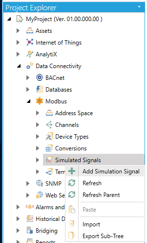
- From the Project Explorer, click on Simulated Signals, then AddSimulation Signal, as shown below.
New Simulation Signal from the Project Explorer
-OR-
Select the Simulated Signals node in the tree explorer, then click on the Add Simulation Signalbutton (shown below) in the Edit section of the Home ribbon in the Workbench.
Add Simulation Signal Button
- This opens New Simulation Signal properties in the right side of the configurator, as shown below. Each Simulation Signal type has specific parameters, as shown below.
Simulation Signal Properties
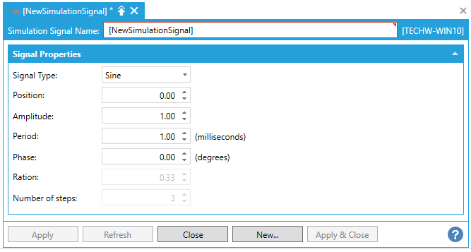
- Name: Specifies the name of the selected simulation signal. The name can be up to 12 alphanumeric characters, including underscores ( _ ) and hyphens ( - ).
Signal Properties
- Signal Type: For each signal, you can select one of the following signal types from the drop-down list:
- Read count is incremented by one every time when the item is read.
- Write count increments when the item is written.
- Random generates random value within the Amplitude range starting with Position.
- Ramp, Sine, Square, Triangle and Step are periodical signals. Their time behavior is influenced by Period and Phase parameters. Period specifies the signal frequency (in milliseconds), while Phase moves the signal origin on the time axis (in degrees).
- Square and Triangle have one additional parameter: Ratio. Ratio defines Triangle signal steepness, or Square signal H/L proportions.
- The Number of steps parameter of the Step signal defines the number of steps into which the signal amplitude will be divided.
- Apply: Saves all changes specified in the properties dialog box. The simulation signal appears in the tree control.
- Reset: Restores the default simulation signal settings.
- Add New: Clicking this button starts configuration of a new simulation signal.
Different Options Available for Simulation Signals
The Simulation Server can be used to generate hundreds of signals. The syntax of the signal determines how it will generate the values. In the next point name syntax, TYPE can be set to Float, Double, Long or Short and is used as a measure for the precision of the simulation.
Period is a value in seconds and
is used to specify the cycle time of the simulation, e.g. 120 will indicate
2 minutes.
Min and Max
specify the lowest and highest value for the simulation.
Phase is in value in 0 - 360 degrees
and is used when multiple signals need to be shifted in phase.
#Steps is a value which indicates
how many steps the signal takes during the 360 degrees cycle.
@sim64:TYPE.Ramp(Period,Min,Max,Phase).Value
@sim64:TYPE.Random(Period,Min,Max,Phase).Value
@sim64:TYPE.Sine(Period,Min,Max,Phase).Value
@sim64:TYPE.Square(Period,Min,Max,Phase).Value
@sim64:TYPE.Triangle(Period,Min,Max,Phase).Value
@sim64:TYPE.Step(Period,Min,Max,#Steps,Phase).Value
@sim64:TYPE.Static("Name").Value
Boolean simulation signals toggle from 1 to 0 (True or False). The "Name" can be changed, e.g. "Pump123" to create a signal which is static, and which can be given a new value using a data entry field in a GraphWorX64 display.
Period is in seconds, Phase
is in degrees.
@sim64:Bool.Square(Period,Phase).Value
@sim64:Bool.Random(Period,Phase).Value
Read/Write signal with custom "Name"
@sim64:Bool.Static("Name").Value
See Also: