Adding Pump Output and Valve Output Control Buttons
To the right of the process points, you will first add the Pump Out control button (Pump 01—Output), which turns the input pump on or off. Then, below the Pump Out button, you will add the Valve Out control button (Valve 01—Output), which opens or closes the selected output valve.
To add a Pump Output and Valve Output control button:
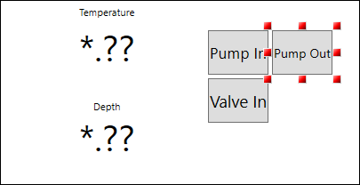
- On the canvas, click the Pump In button and select Ctrl+D to duplicate it (the duplicated button retains the Pump In Dynamic Behavior properties).
- Double-click the duplicated button, and enter Pump Out, then click and drag the button to next to the Pump In button.
 After duplicating the button, make sure the existing Pick action (located at the top section of the Dynamics panel) is selected to ensure the correct dynamics properties appear for the Pump Out control button.
 - In the Dynamics panel, do the following:
- In the Data section, select DataSource and click
 to open the Data Browser.
 - From the Data Browser Data Points tab, expand Assets > Tank Farm Management System > Pumps .
- Select Pump 01 - Output as the data source (tag) and click OK.
- Select Dynamic Behavior > CommandParameters, and then enter the following values:
- ValueOne: 0
- ValueTwo: 1
- In the Data section, select DataSource and click
- At the top of the Dynamic panel, click
 to add and define the button Color actions.
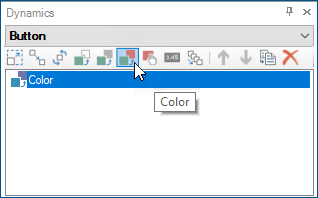
- Define the button's color data source.
- In the Data section, select DataSource and click to open the Data Browser.
- From the Data Browser Data Points tab, select Assets > Tank Farm Management System > Pumps.
- Select Pump 01 -Output as the data source (tag) and click OK.
- In the Data section, select DataSource and click
- Verify the following Dynamic Behavior button background and color settings and click OK.
- Select TargetPropertyName, then select Background from the list (if necessary).
- Select EndColor and click the ellipsis, picking a green color from the Solid Color tab (if necessary).
- Define the button's color data source.
- Add the Valve Out control button:
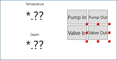
- On the canvas, right-click the Valve In button and select Ctrl+D to duplicate it (the duplicated button retains the Valve In Dynamic Behavior properties).
- Double-click the duplicated button, enter Valve Out, and then click and drag the button below the Valve In button.
 After duplicating the button, make sure the existing Pick action (located at the top section of the Dynamics panel) is selected to ensure the correct dynamics properties appear for the Valve Out control button.
 - In the Dynamics panel, do the following:
- In the Data section, select DataSource and click to open the Data Browser.
- From the Data Browser Data Points tab, expand Assets > Tank Farm Management System > Valves .
- Select Valve 01 - Output as the data source (tag) and click OK.
- Check the button's dynamic behavior—the CommandParameters values, the TargetPropertyName background, and the EndColor is green. (See steps 3 c and 4 b.)
- In the Data section, select DataSource and click
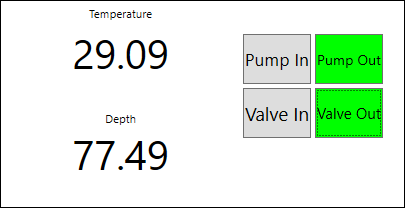
- To view the button's interaction with the rising Depth value, sRuntime in the upper right corner, and then do the following:
- Press the Pump In and Valve In buttons to stop the tank from filling. The Depth will stop rising.
- Press the Pump Out and Valve Out buttons. When activated, the buttons turn green. You may notice a slight delay after turning on the pump and opening the valve, which is designed.
- When finished, click Configure in the upper right corner to return to the configuration mode.
- In the toolbar, click File > Save.
What's Next?