FREQROL Template Display Specifications
FREQROL Template Version 1 consists of a list screen and detail screens. The images of each screen are shown below.

Screen Specifications
|
No. |
Items |
File Format |
Description |
||
|---|---|---|---|---|---|
|
1 |
List screen |
GDFX |
Displays a list of connected inverters. [File Name] listing.gdfx |
||
|
2 |
Detail screens |
GDFX |
Displays details of the selected inverter. [File Name] equipment_detail.gdfx |
||
|
3 |
|
Overview screen |
GDFX |
Displays the main monitor items for the inverter. [File Name] overview.gdfx |
|
|
4 |
Trend screen |
GDFX |
Displays trend graphs of inverter monitor items. [File Name] Trends.gdfx |
||
|
5 |
Monitor screen |
GDFX |
Displays all inverter monitor items. [File Name] equipment_detail.gdfx |
||
|
6 |
Parameter screen |
GDFX |
Displays the main parameters of the inverter. [File Name] equipment_detail.gdfx |
||
|
7 |
Alarm screens |
GDFX |
Displays screens related to inverter alarms. [File Name] alarms.gdfx |
||
|
8 |
|
Alarm (equipment) screen |
GDFX |
Displays the alarm history stored inside the inverter (8 to 10 items depending on the model). [File Name] alarms.gdfx |
|
|
9 |
Alarm (history) screen |
GDFX |
Displays the alarm history of the inverter recorded by Alarm Historian. [File Name] alarms.gdfx |
||
|
10 |
Alarm (by type) screen |
GDFX |
Displays the inverter alarm history recorded by Alarm Historian, grouped by alarm type. [File Name] alarms.gdfx |
||
The configuration and image of each display are shown below.
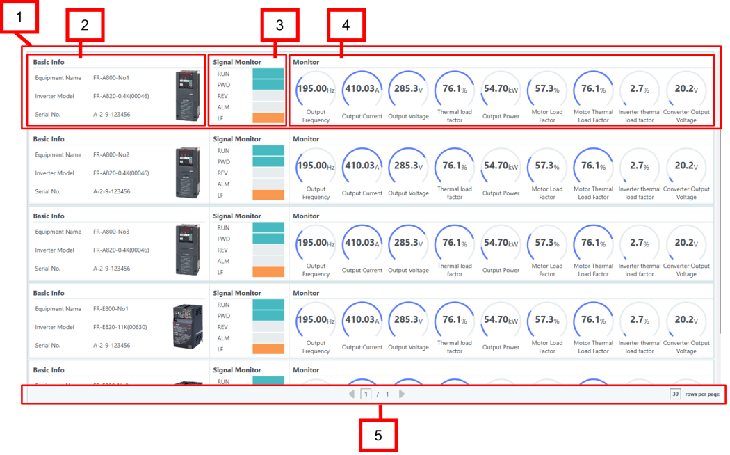
List Screen
The list screen displays a list of connected inverters. The screen image and configuration are shown below.
|
No. |
Name |
Description |
|
|---|---|---|---|
|
1. |
Faceplate |
Displays an overview of the connected inverter. |
|
|
2. |
|
Basic info |
The inverter model name, etc. |
|
3. |
Signal Monitor |
The output signal status. |
|
|
4. |
Monitor |
The main monitor items. |
|
|
5. |
Page forwarding |
Operates page forwarding on the list screen. |
|
Detail Screen
The details screen contains tabs for the Overview, Trend, Monitor, Parameter, and Alarm displays. The screen image and configuration are shown below.

|
No. |
Name |
Description |
|---|---|---|
|
1. |
Overview tab |
Loads the overview screen. |
|
2. |
Trends tab |
Loads the trend screen. |
|
3. |
Monitor tab |
Loads the monitor screen. |
|
4. |
Parameters tab |
Loads the parameter screen. |
|
5. |
Alarm tab |
Loads the alarm screen. |
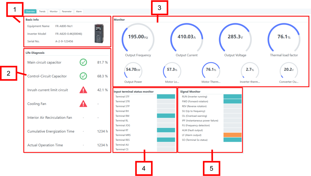
Overview Screen
The overview screen displays the main information for the selected inverter. The screen image and configuration are shown below.
|
No. |
Name |
Description |
|---|---|---|
|
1. |
Basic info |
Displays the inverter model name, etc. |
|
2. |
Life Diagnosis |
Displays the inverter’s lifespan. |
|
3. |
Monitor |
Displays the main monitor items. |
|
4. |
Input terminal status monitor |
Displays the input terminal status. |
|
5. |
Signal Monitor |
Displays the output signal status. |
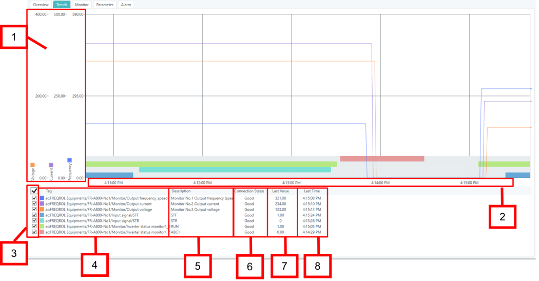
Trend Screen
The trend screen displays trend graphs of inverter monitor items. The screen image and configuration are shown below.
|
No. |
Name |
Description |
|---|---|---|
|
1. |
Monitor value (Y axis) |
Displays the monitored items and input/output terminal status obtained from the inverter on a trend graph. Displays the following monitored items as line graphs by default:
Displays the following input/output terminal statuses as event bar graphs (graphs where the duration of the On state is shown as a band) by default:
|
|
2. |
Current Time (X axis) |
Displays a graph from the current time to the set time range. The default range is 5 minutes. You can change the time range in runtime or by editing the GraphWorX display. |
|
3. |
Checkboxes |
Select the monitor items to display in the graph. When selected, the graph displays the corresponding item. The graph does not display unselected (unchecked) items. |
|
4. |
Tag |
Displays the Asset path. |
|
5. |
Description |
Displays a description of the Asset path. |
|
6. |
Connection Stat |
Displays the connection status (Good/Bad). |
|
7. |
Last Value |
Displays the most recent value. |
|
8. |
Last Time |
Displays the time when the most recent value was obtained. |
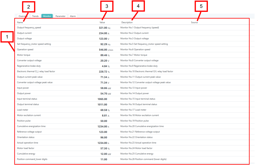
Monitor Screen
The monitor screen displays all the inverter monitor items. The screen image and configuration are shown below.
|
No. |
Name |
Description |
|
|---|---|---|---|
|
1. |
Monitor screen |
Monitors all inverter monitor items at once. |
|
|
2. |
|
Name |
The device property name of the monitored item. |
|
3. |
Value |
The current value of the monitored item obtained from the inverter. |
|
|
4. |
Description |
The description of the monitored item. |
|
|
5. |
Source |
The data points of the monitored item. |
|
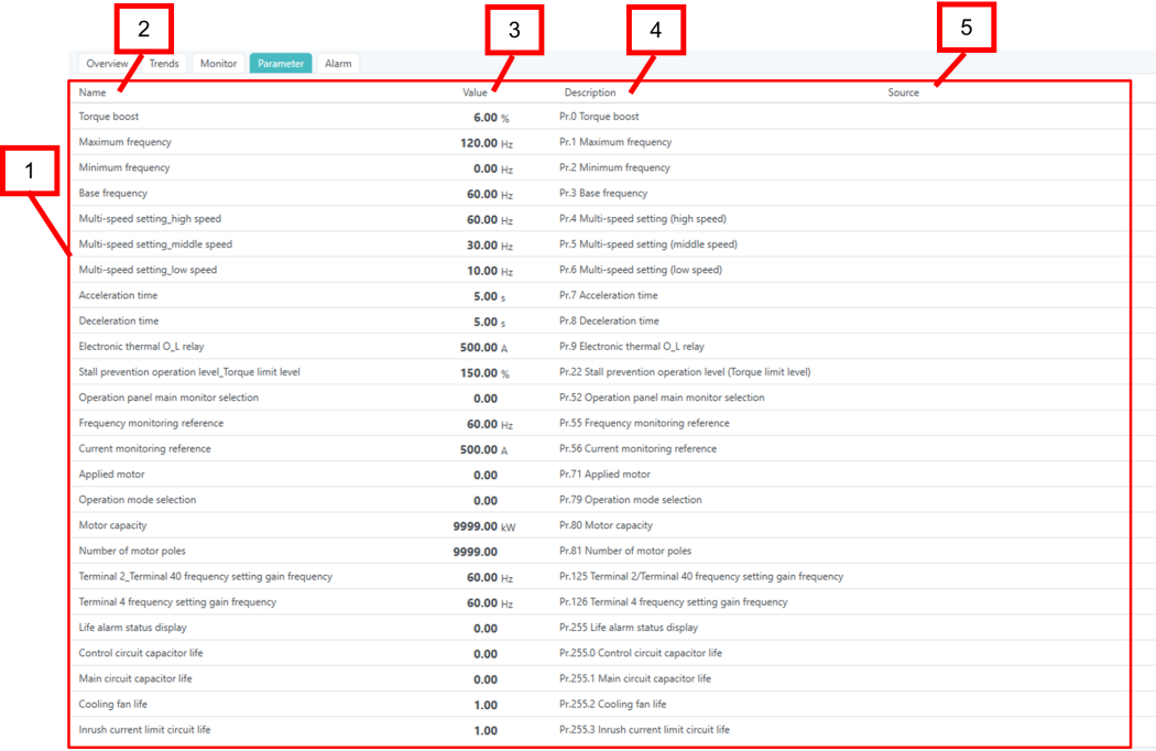
Parameter Screen
The parameter screen displays the main parameters of the inverter. The screen image and configuration are shown below.
|
No. |
Name |
Description |
|
|---|---|---|---|
|
1. |
Parameter screen |
Displays the main parameters of the inverter. |
|
|
2. |
|
Name |
The device property name of the parameter. |
|
3. |
Value |
The current value of the parameter obtained from the inverter. |
|
|
4. |
Description |
The parameter description. |
|
|
5. |
Source |
The parameter data points. |
|
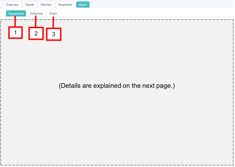
Alarm Screens
Selecting each tab on the Alarm screen will display the corresponding screen. The screen image and configuration are shown below.
|
No. |
Name |
Description |
|---|---|---|
|
1. |
Equipment tab |
Loads the Alarm (equipment) screen. |
|
2. |
Historical tab |
Loads the Alarm (history) screen. |
|
3. |
Chart tab |
Loads the Alarm (by type) screen. |
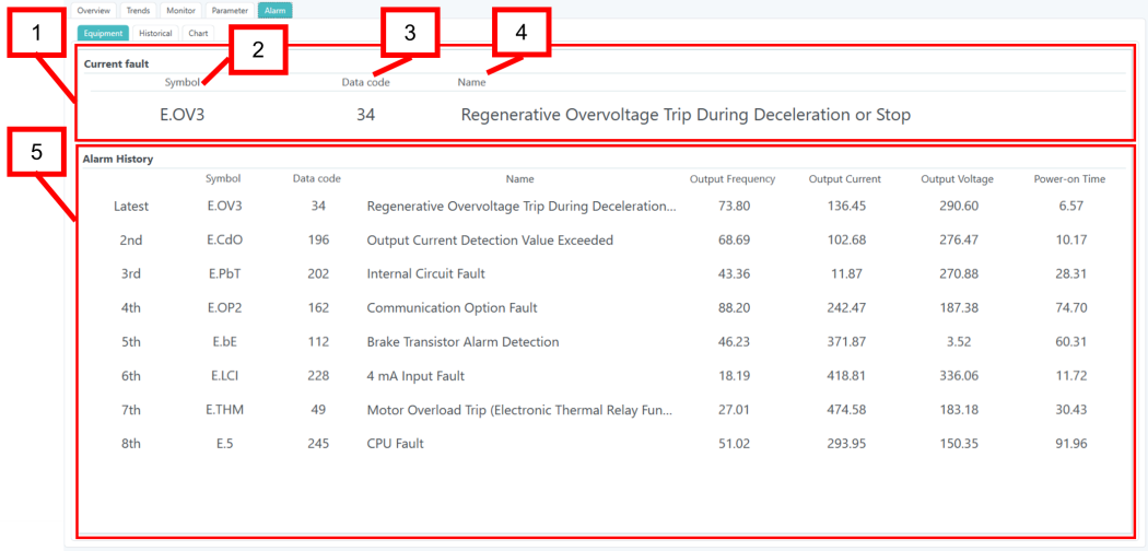
Alarm (Equipment) Screen
The Alarm (equipment) screen displays information on current alarms and the alarm history (maximum of 8–10 alarms, depending on the model) stored inside the inverter. The screen image and configuration are shown below.
|
No. |
Name |
Description |
|
|---|---|---|---|
|
1. |
Current fault |
Displays information about current alarms. If no alarms have occurred, the system displays “-“ in each field. |
|
|
2. |
|
Symbol |
The symbol corresponding to the data code of the latest alarm in the formula of the Asset device properties. If the data code is unknown, the system displays “-“. |
|
3. |
Data code |
The data code of the latest alarm from the alarm history stored inside the inverter during an alarm occurrence. |
|
|
4. |
Name |
The name corresponding to the data code of the latest alarm in the formula of the Asset device properties. If the data code is unknown, the system displays “- (Unknown error)”. |
|
|
5. |
Alarm History |
Displays the alarm history (maximum of 8-10 items depending on the model) stored inside the inverter. If there is no alarm history stored inside the inverter, the system displays “-“ for each item. |
|
|
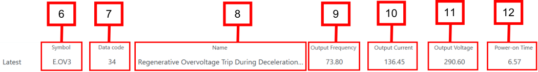
6. |
|
Symbol |
The symbol corresponding to the data code of the alarm history in the formula of the Asset device properties. If the error number is unknown, the system displays “-“. |
|
7. |
Data code |
The data code from the alarm history stored inside the inverter during an alarm occurrence. |
|
|
8. |
Name |
The name corresponding to the data code of the alarm history in the formula of the asset device properties. If the data code is unknown, displays “- (Unknown error)”. |
|
|
9. |
Output Frequency |
The output frequency at the time of the alarm history occurrence stored inside the inverter. |
|
|
10. |
Output Current |
The output current at the time of the alarm history occurrence stored inside the inverter. |
|
|
11. |
Output Voltage |
The output voltage at the time of the alarm history occurrence stored inside the inverter. |
|
|
12. |
Power-on Time |
The power-on time at the time of the alarm history occurrence stored inside the inverter. |
|
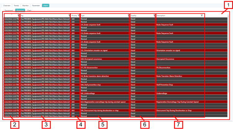
Alarm (History) Screen
The Alarm (History) screen displays the inverter alarm history recorded by Alarm Historian. The screen image and configuration are shown below.
|
No. |
Name |
Description |
|
|---|---|---|---|
|
1. |
Alarm (history) screen |
Displays and records the latest alarm from the alarm history stored inside the inverter using GENESIS Alarm Historian (alarm recording function). Select a heading to sort or filter the alarms. By default, it sorts in descending time order. The alarm history on this screen and the error history on the Alarm (equipment) screen have different information sources, so the number and content (time of occurrence, order of occurrence, etc.) that is displayed may differ. The alarm history that is displayed on this screen is information recorded by GENESIS Alarm Historian (alarm recording function). The alarm historythat is displayed on the Alarm (equipment) screen is information stored inside the equipment (information that disappears when the inverter is turned off, etc.). |
|
|
2. |
|
Time/Date |
The date and time when GENESIS detected the specific alarm |
|
3. |
Tag |
The path of the equipment instance that detected the alarm. |
|
|
4. |
Priority |
The severity of the alarm. |
|
|
5. |
Type |
The type of the alarm. |
|
|
6. |
Quality |
The quality of the alarm. |
|
|
7. |
Description |
The description of the alarm content. |
|
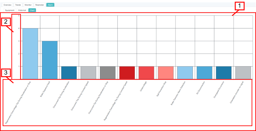
Alarm (By Type) Screen
The Alarm (by type) screen displays the inverter alarm history recorded by Alarm Historian, grouped by alarm type. The screen image and configuration are shown below.
|
No. |
Name |
Dscription |
|
|---|---|---|---|
|
1. |
Alarm (by type) graph |
The alarms recorded by Alarm Historian as graphs categorized by type (data code). Displays up to 1000 alarms recorded in the inverter template, sorted by the oldest of the day by default. |
|
|
2. |
|
Number of alarms (Y axis) |
The number of alarms that have occurred. |
|
3. |
Alarm type (X axis) |
Alarms by type (data code). |
|