Solid Color, Gradient, and Image Tabs
From the GraphWorX64 3D ![]() Materials ribbon, select a 3D object and click
Materials ribbon, select a 3D object and click ![]() Front or Back material,
Front or Back material,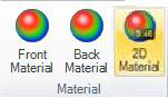 then from the dialog box click any box in the Material section to access the Color dialog box's Solid Color, Gradient, and Image tabs. (The Color dialog box also displays when used in the Styles and Colors section of the 2D Home ribbon.) For supplemental information, refer to the Material Section topic.
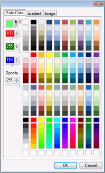
Solid Color Tab
Use the ![]() Solid Color tab to select a color, create a color, or change the opacity. Simply click the color you want to apply. The Solid Color tab has an eye dropper tool for copying color from one object to another.
Solid Color tab to select a color, create a color, or change the opacity. Simply click the color you want to apply. The Solid Color tab has an eye dropper tool for copying color from one object to another.
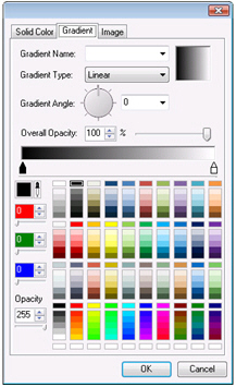
Gradient Tab
Use the ![]() Gradient tab to set a gradual radiance to the selected color. Fields on the tab include:
Gradient tab to set a gradual radiance to the selected color. Fields on the tab include:
-
 Gradient Name — There are several gradients for you to choose from.
 -
Gradient Type:
-
-
Radial
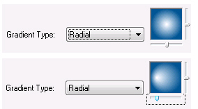 (the gradient radiates from a central point). You can adjust the radial gradient by either the vertical or horizontal sliders. Drag the sliders to reposition the center point form which the color radiates.
 -
Linear
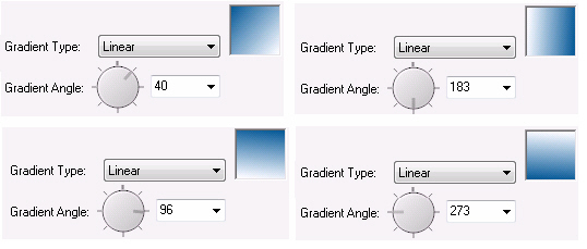 (the gradient changes in one direction) You specify a Gradient Angle from which the color will transition to fade.
 -
-
Gradient Angle — To do this, you can click on the dial to move it, type the angle number in the box (0 to 360), or select from the drop-down list (the choices of 0, 45, 90, 135, 180, 225, 270, and 315, define the angle emanating from the sides and corners of the box). As you change the gradient angle, you can see the effect in the color box.
-
-
Overall Opacity
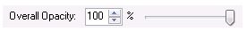 — Set the overall opacity of the gradient. You can type, scroll, or use the slider to set a percentage from 100% (full color) to 0% (no color).
 -
Color Bar
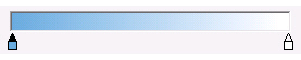 - You can select or set a color. The color you create displays in the color bar in the middle of the tab.
 -
Eye dropper tool is used for copying color from one object to another.
-
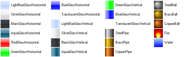
Image Tab
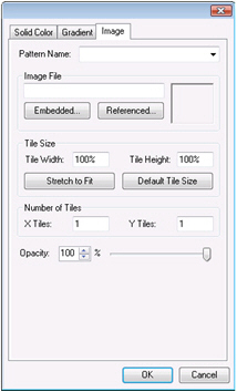
Use the ![]() Image tab to paste an image or picture onto the surface of the selected object. Such images are called
Image tab to paste an image or picture onto the surface of the selected object. Such images are called ![]() textures. There are several ways in which you can apply and manipulate images on the surfaces of your 3D objects using the Image tab. The fields on the Image tab are:
textures. There are several ways in which you can apply and manipulate images on the surfaces of your 3D objects using the Image tab. The fields on the Image tab are:
-
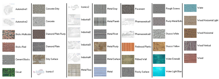
Pattern Name You can apply a pattern provided by ICONICS. For example, you may have a Plane primitive object that you are using for a floor in your packing plant; you might want to apply the Concrete Dirty or Metal Floor or Wood pattern, so that it looks like the floor in your packing plant. These patterns also serve as examples of images you can create for your own use. For example, you can create a JPEG file of your own company logo to apply to surfaces in the 3D views that you create. If you have created your own images, you apply them by using the Image File section of the tab.
-
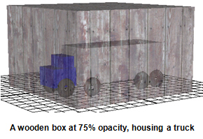
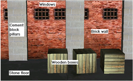
Image File You can apply an image from any source. For example, you can apply the photograph of a city skyline to be used as a background. You can apply a bitmap of your company logo to apply to the sides of trucks. You can copy images of windows off the internet which you use in an image of a brick wall that you then apply to warehouse walls in a 3D view. You can use any image; any format can be applied to an object. Note that you can’t edit the image in GraphWorX64; you can only stick it onto an object.
-
You can embed an image in the GraphWorx64 display (click the Embedded button to search for a file) An embedded image enlarges the size of the GraphWorX64 display file, but the image “travels” with the GraphWorx64 display wherever you install it.
-
Reference an image file that is stored elsewhere (click the Referenced button to search for a file). . A referenced image allows the image to be sourced externally to the GraphWorx64 display so that it doesn’t enlarge the size of the GraphWorx64 display file; but if you want the GraphWorx64 display file to be portable, you need to remember to include it (and all other referenced image files) with the display wherever you install it.
-
Tile Size - The default Tile Width and Tile Height is 100%. You can reduce the size of the image or make it larger. Note, however, that clicking the Default Tile Size button does not automatically restore the tile to 100%. If the Default Tile Size does not restore the tile to the size you want, type 100% (including the % sign) in each of the fields. Entering a value in the Tile Width field overrides the value in the X Tiles field, and vice versa. Likewise, entering a value in the Tile Height field overrides the value in the Y Tiles field, and vice versa.
-
Click the Stretch to Fit button to stretch the image to spread it over the surface. This is the default condition for images that you apply to the surface of an object; it sets the tile width and height to 100% and sets the number of X and Y tiles to 1.
-
Click the Default Tile Size button to set the image to its default size. Note that the default size may not be the desired size; instead, you may want to type 100% in the Tile Width and Tile Height fields.
-
X Tiles and Y tiles - Tiles applied to surfaces are two-dimensional; as such, you can specify how many tiles you want displayed horizontally (along the x-axis) and vertically (along the y-axis) on the object’s surface. Decimals are allowed; the number of tiles is limited only by the appearance you are trying to achieve. Entering a value in the X Tiles field overrides the value in the Tile Width field, and vice versa. Likewise, entering a value in the Y Tiles field overrides the value in the Tile Height field, and vice versa.
-
Opacity - If you want the image to be opaque (that is, transparent), enter the percentage of opacity by typing the percentage (0 to 100) into the field, using the number scroll, or the slider to the percentage. By default, the opacity is set to 100% (that is, no opacity).