3D Transformations and Mirroring
GraphWorX64 offers the capability to move selected 3D objects and transform object faces using the advanced transformation buttons in the ![]() Transform section on the 3D Home ribbon. The Transform section contains options that let you move the selected object in relation to the X axis, Y axis, or Z axis and transform the face of a selected object. Each option is described below.
Transform section on the 3D Home ribbon. The Transform section contains options that let you move the selected object in relation to the X axis, Y axis, or Z axis and transform the face of a selected object. Each option is described below.
Transform Button 
Click the Transform button in the Transform section to move, rotate, or scale the selected object(s) by numeric precision along any of the three axes. This button provides the same changes that are available with the Move, Rotate, and Scale buttons in the Manipulator section, except with the Transform button you can be more precise. When you click this button, the dialog box shown below appears so that you can explicitly state the changes you want by entering numeric values.
Options for moving, rotating, and scaling a 3D object
![]()
|
|
Note: Any Snap Options that are activated will override the values you enter in this dialog box. |
-
Translate fields - Enter a value to move the selected object(s). Specify the number of units along the x-, y-, and/or z-axis that you want to move the object. To calculate the exact number of units, turn on the grid for the axis along which you want to move the object; each line in the grid represents one (1) unit. To leave the object where it is, enter 0 (zero) in each Translate field. If the Grid Snap option is activated, the move will snap the object to the closest grid.
-
Rotate fields - Enter a value to rotate the selected object(s). Specify the number of degrees you want to rotate the object around the x-, y-, and/or z-axis. To leave the object unrotated, enter0(zero) in each field. If theAngle Snapoption is activated, the rotation will snap to the closes angle.
-
Scale fields - Enter a value to resize the selected object(s). Specify the scaling factor that you want to use to expand or reduce the object along the x-, y-, and/or z-axis. For example, to double its size along the y-axis, enter 2 in the Y column; to halve the object’s length along the z-axis, enter 0.5 in the Z column. If the Grid Snap option is activated, the resizing will snap the edge of the object to the closest grid. To leave the object’s size unchanged, enter1(one) in each Scale field.
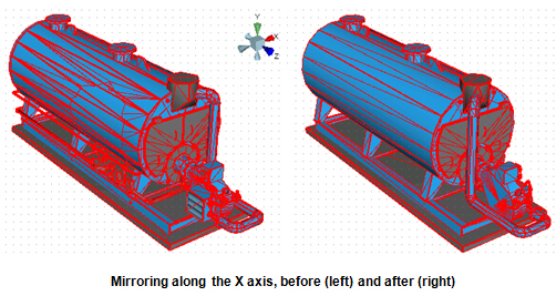
Mirror X Button 
Click the Mirror X button (or press the MX ![]() hot key ) to shift the selected object to its mirror position along the X axis. The
hot key ) to shift the selected object to its mirror position along the X axis. The ![]() object is repositioned just as shown on the button.
object is repositioned just as shown on the button.
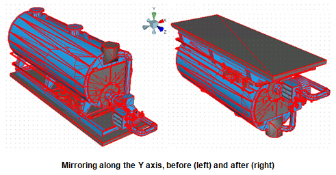
Mirror Y Button 
Click the Mirror Y button (or press the MY ![]() hot key ) to shift the selected object to its mirror position along the Y axis. The
hot key ) to shift the selected object to its mirror position along the Y axis. The ![]() object is repositioned just as shown on the button.
object is repositioned just as shown on the button.
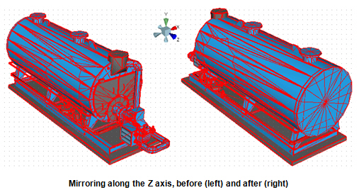
Mirror Z Button 
Click the Mirror Z button (or press the MZ ![]() hot key ) to shift the selected object to its mirror position along the Z axis. The
hot key ) to shift the selected object to its mirror position along the Z axis. The ![]() object is repositioned just as shown on the button.
object is repositioned just as shown on the button.
Extrude Face Button 
You can extrude a face of an object by using the Extrude Face button. This button becomes available only when the Face selection button is selected in the Selection Mode section on the Home ribbon.
To use this button:
-
Click the Face
button in the Selection Mode section of the Home ribbon. -
Select the object face that you want the extrusion added to.
-
Click the Extrude Face
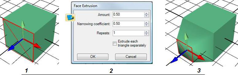
button in the Transform section of the Home ribbon. The Face Extrusion dialog box appears. -
Specify the Amount by which you want the face to extrude from the object. For example, .50 makes the extrusion protrude from the object by 50% of the object's depth.
-
In the Narrowing Coefficient field specify the amount by which you want it to narrow. For example, .50 reduces the extruding region by 50%.
-
In the Repeats field specify the number of times you want the extrusion to repeat. For example, if you enter 2, the Amount and Narrowing Coefficient will be applied once, and then it will be applied a second time to the face.
-
If you want each triangle in the face to extrude independently, put a checkmark in the Extrude Each Triangle Separately checkbox.
-
Click OK when you are done.
An Example of the Face Extrusion process
Divide Face Button
You can divide the selected face of an object into more parts or vertices by using the Divide Face button. This button becomes available only when the Face selection button is selected in the Selection Mode section on the Home ribbon.
Use this button when you want to be able to select a more finite triangle of the face. The following example shows how a 12-triangle face becomes a 36-triangle face after clicking this button.
Using the Divide Face Button
![]()
Turn Selected Edge Button 
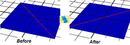
You can turn the selected edge of a face on an object by using the Turn Selected Edge button. This button becomes available only when the Select Edges button  is selected in the Selection Mode section on the Home ribbon. The following example shows how the selected edge (marked in red) of a two-faced plane turns when you click this button.
Using the Turn Selected Edge Button
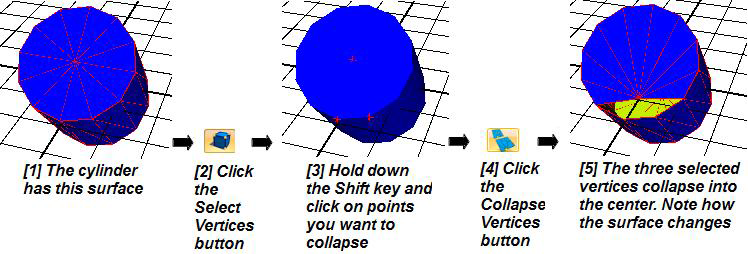
Collapse Selected Vertices Button 
You can collapse the selected vertices on an object by using the Collapse Selected Vertices button. This button becomes available only when the Select Vertices button  is selected in the Selection Mode section on the Home ribbon. The following example shows how three selected vertices on a cylinder primitive change the surface area of the cylinder when you use this button.
Using the Collapse Selected Vertices Button