Devices
In the Modbus Configurator, a device represents a hardware device that communicates with the OPC server over TCP/IP or serial port (RS-232). A device is directly communicating with its socket, so it is logically under the first level in the Address Space tree. Again, the device is represented by its symbolic name. Also, its IP address in combination with the unit identifier value uniquely identifies the device. It is impossible to have two devices with the same IP address. Setting up a device requires configuring its IP address, unit identifier, TCP port, type, timeouts and optimization parameters.
Setting up a device requires configuration of its unique address, type, timeouts and optimization parameters, as shown in the figure below.
To Add a New Device:
-
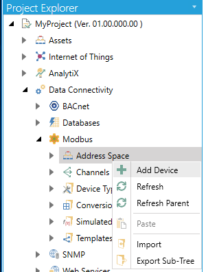
From the Project Explorer, click on Address Space, then Add Device, as shown below.
New Device from the Project Explorer
-OR-
Select the Address Space node in the Project Explorer, then click on the Add Devicebutton (shown below) in the Edit section of the Home ribbon in the Workbench.
Add Device Button

-
This opens the New Device properties in the right side of the configurator, as shown below. In the DeviceName field, specify a name for the new device.
Configuring a New Device
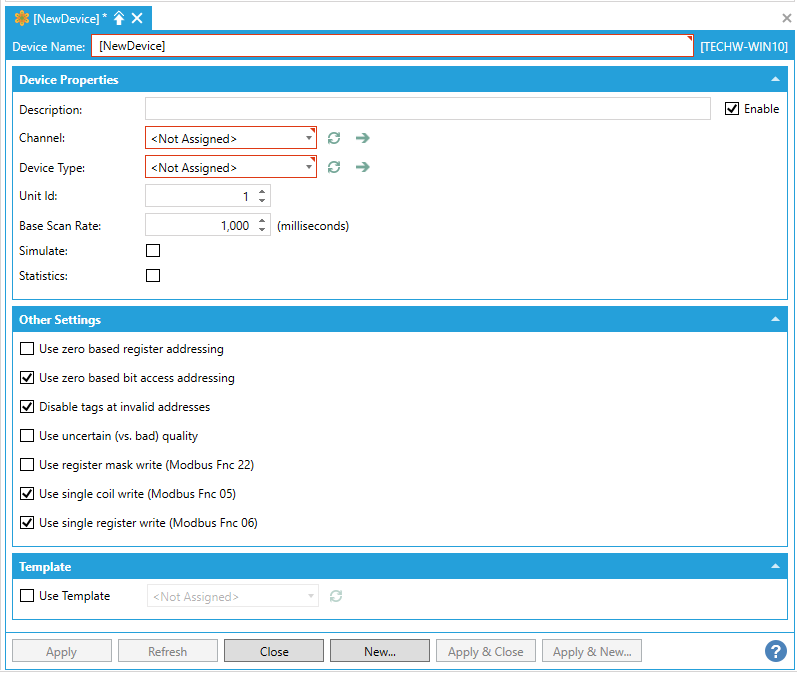
Device Properties
-
Enable - Click this checkbox to enable to the selected device.
-
Description - Enter a description of the device in the text entry field. This will help to differentiate individual devices when multiple items are configured.
-
Channel - Use the pulldown menu to select from listed Channels. Click on the
 button to refresh the list. Click
on the
button to refresh the list. Click
on the  to
open an additional window containing the selected Channel's
properties.
to
open an additional window containing the selected Channel's
properties. -
Device Type - Use the pulldown menu to select a Device Typefrom among those listed (Default Device Type, Ideal, Micro 84, ModCell, Modicon 184, Modicon 384, Modicon 484, Modicon 584, Modicon 584L, Modicon 884, Modicon 984, Quantum, Simple ).Click on the
button to refresh the list. Click
on the to
open an additional window containing the selected Device
Type's properties. -
Unit Id -The Unit Identifier field may be used to communicate via devices such as bridges and gateways that use a single IP address to support multiple independent end units.
-
Base Scan Rate - This sets the rate, in miliseconds, at which the data will be polled from the device. 0 = the scan rate based on OPC requests. Fast scan rates may have impact on a device's responsiveness.
-
Enable Simulation - Click on this checkbox if this device should be considered as simulated only.
-
Enable Statistics -
Other Settings
-
Use zero based register addressing - Enables "Zero vs. One"-based addressing of coils and registers (at Data Item level).
-
Use zero based bit access addressing - Enables "Zero vs. One"-based register Bit-Access addressing (at Data Item level).
-
Disable tags at invalid addresses - Enables disabling of polling of tags that are detected at invalid device addresses.
-
Use uncertain (vs. bad) OPC quality - Allows for reporting of data with uncertain OPC quality when the device is disconnected and good data was previously known.
-
Use register mask write (Modbus Fnc 22) - Enables writing of bit-access data into a device using Modbus function 22 (Mask Write Register). The device/vendor must support this Modbus function.
-
Use single coil write (Modbus Fnc 05) - Uses Modbus function 05 (Write Single Coil) to write into a single coil. Otherwise, Modbus function 15 (Write Multiple Coils) will be used. Note that the Modbus function 05 may not be implemented by all Modbus devices/vendors, while Modbus function 15 is usually implemented by all devices/vendors.
-
Use single register write (Modbus Fnc 06) - Uses Modbus function 06 (Write Single Register) to write into a single register. Otherwise, Modbus function 16 (Write Multiple Registers) is used. Note that Modbus function 06 may not be implemented by all Modbus devices/vendors, while the Modbus function 16 is usually implemented by all devices/vendors.
Template
-
Use Template - Click this checkbox if you wish to use a preconfigured template to set the properties for your selected device. Once checked, this activates the nearby pulldown menu where you can select from existing Templates. Click on the
button to refresh this list with
any recent changes to the listed Templates.
Suspended Mode Settings (Channel-level override)
-
Override Suspended Mode
-
Timeouts to suspend - If selected, enter a number of timeouts to suspend in the text entry field (or use the up/down arrow buttons).
-
Suspended period - Enter a suspended period (in milliseconds) in the text entry field (or use the up/down arrow buttons).
-
Once you have completed making your settings, click on the Apply (or Apply & Close) button to save your changes and return to the Workbench.
See Also: